We often come across a situation where we want to turn on an electrical load by pressing some buttons in a computer program. Consider an example, where you are sitting in a power plant and you want to turn on a circuit breaker remotely. Controlling the circuit breaker from a remote location can be achieved using a micro controller. We will discuss how to make one.
Remote Control Circuit Breaker Using a Micro controller.
- Micro controller (such as an Arduino).
- Transistor.
- Diode.
- Resistors.
- Relay.
- LED.
- PC (Personal Computer).
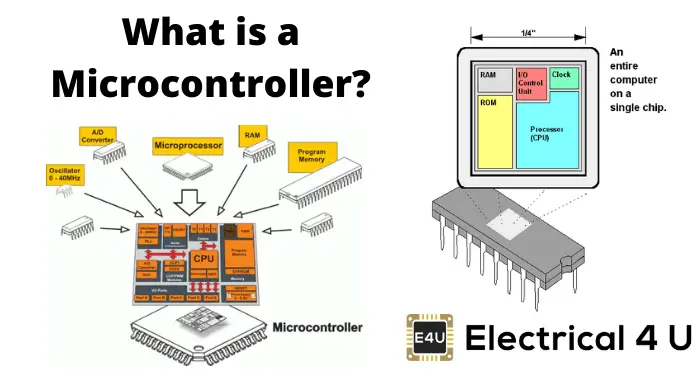
Micro controller:
A micro controller is an IC that has the intelligence to understand the commands received from the PC through a communication protocol. A micro controller has various communication protocols to communicate with a PC such as Serial, Ethernet and CAN (Controller Area Network) communication protocols.
A micro controller has many peripherals like GPIO (General Purpose Input Output) pins, ADC (Analog to Digital Converter), Timer, UART (Universal Asynchronous Receiver Transmitter) and Ethernet to communicate with the outside world. There are peripherals.
The digital output from the micro controller is a low amperage signal.
When you set a pin high, the voltage on that pin is usually +3.3V or +5V and the amperage it can source or sink is around 30mA. This is fine if you are controlling an LED that needs very little.
If we want to control a circuit breaker through a micro controller pin, we need a driver that can supply the required amount of current to the load to turn the switch on. You need a component between your micro controller and the device that will be controlled with a small voltage and current. Relays and transistors are often used for this purpose.
Transistor:
The transistor acts as a driver in this application to supply the required current to the relay so that it turns on in saturation mode.
Resistor:
Resistors are used to limit the current in LEDs, transistors.
LED:
A light emitting diode is used to indicate whether the circuit breaker is on or off.
Relay:
A light emitting diode is used to indicate whether the circuit breaker is on or off.
Working Principle of Remote Controlling of Circuit Breaker by Micro controller:
When giving a command to the micro controller to turn on the load, the micro controller pin is set to 3.3V (in the above circuit) which turns on the NPN transistor. When the transistor turns on, current flows from the collector to the emitter of the transistor which energizes the relay and the relay connects the AC voltage to the circuit breaker which turns the circuit breaker on.
The An LED is used to indicate whether the circuit breaker is on or off. When the micro controller pin is high, the LED is on (circuit breaker on) When the micro controller pin is low, the transistor is in the off state and no current flows through the relay coil and the circuit breaker is off, L ED also turns off.
Protection Diode:
When the relay is closed, a back e.m.f is generated which can damage the transistor if the magnitude of the back e.m.f is greater than the VCEO voltage of the transistor. A diode is used to protect the transistor as well as the digital output of the micro controller which conducts when the relay is closed. It is also called a freewheeling diode.